Major Piping deliverable’s issued in Piping Design
Piping deliverable’s are the major products of piping design, represents the actual design of piping in to drawings and documents. Every drawings and documents are prepared to fulfil certain requirement’s of a project.
The intent of piping deliverable’s is to facilitate the construction team to understand the installation’s, to execute the construction of the project.
Here i have listed the major Piping deliverable’s issued in Piping design in all the industries.
If you are,
An aspiring piping design engineer, you must master the below deliverable’s to become an expert in piping.

The Major Piping deliverable’s are:
1) Unit Plot Plan
2) Piping Layout
3) Piping Isometric
4) MTO
5) Tie-in List
1. Unit Plot
Unit Plot Plan is a part of a main plot plan. The Main Plot plan of a process plant represents the whole plot area of the Plant, which is further divided in to many small units based on the processing of unit. Each unit will be given with individual names and developed in the individual drawings. The plot plan for an individual unit is named as Unit Plot Plan.
In general , all the plot plan consist details of equipment’s, co-ordinates, finished floor elevations, pipe racks, access roads, battery limit fence, Unit entry & Exit, trenches etc. Refer the unit plot plan in the below figure.
The basis of making of Unit plot plan, is entirely different from the basis of making of Main plot plan. The main plot plan involves more study in to process and technical safety, general safety and hazards, product management, fire protections, emergency plan, future expansions, environmental and occupational safety etc.
Where as , the aspect of unit plot is to ensure that all the equipment’s are placed in such a way to ease the process cycle, accessibility, maintenance and operation.
2. Piping Layouts
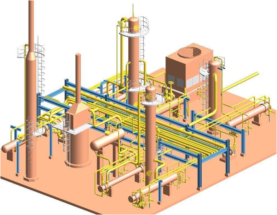
Piping layouts are commonly referred as piping general arrangement drawings (GA), is an Orthographic piping drawings shows all the details in a given area, such as piping’s, equipment’s, pipe-racks, platforms, ladders, valves, supports, instruments and cable trays etc.
Piping GA’s are the most detailed drawings developed after conducting lots of iterations of piping studies and research.
Piping layouts are the first set of drawings to be prepared in process piping design and it goes on including all the latest information’s from other disciplines such as civil, structural, electrical, instruments, safety, process and equipment’s, until it is issued for construction.
To master piping layout, one should have a knowledge on international design codes and standards, equipment placements, various type of equipment’s, pipe routing, pipe rack, pipe supports, basic’s of pipe stress, process piping engineering, operation and maintenance requirements.
The intent of the piping layout is to develop the most economical and value-added piping model.
3. Piping Isometric
Piping isometric is a 3-Dimensional drawing representing the actual pipe routing w.r.t North, south, east and west co-ordinates.
Actual construction is done only based on Piping isometrics, as it consists details such as pipe routing, co-ordinates, support details, BOM, test pressure, insulation and painting.
Piping isometric is the most important drawing for construction, fabrication, installations, testing and inspection.
4. MTO – Material Take-off
MTO consist the list of piping materials to be procured for construction.
MTO’s is a document prepared for a specific project which includes materials required for construction.
Generally MTO’s are done at 3 stages of the project life cycle. The first at 30% completion of the project,the second is at 60 % and the third is at 100% completion.
MTO generation is a very responsible activity as missing out a material from the list , shall lead to a construction delay.
5. Tie-in List
Tie-in List is a document that shows the list of Tie-in points. Tie-in point is a term that refers to a place at which the piping is going to be connected with an existing or other new facilities. Generally, the Tie-in’s are done either with an equipment’s or with an existing piping.
The tie-in list consists the details such as to and fro line numbers, equipment numbers, Tie-in no’s, Pipe spec, type of Tie-in ( Flanged or welded), rating and schedule of Tie-in.
 (1).png)

 Prakash K Menon


